
Tekla Structural Designer 2021 SP4 Update | 107.4 mb
Trimble launched Tekla Structural Designer 2021 SP4 (21.4.0.72). This release includes a number of new features, enhancements and issue resolutions as detailed below.
Tekla Structural Designer 2021 SP4 (21.4.0.72) release notes
Highlights
- Automatic minimum wind loads - USA head code
- Steel column base plate design - enhanced design for minor axis shear - Eurocode
- Embodied carbon - New and enhanced review & reporting options
-[TSD-9854] - IS (Indian) Head Code generated orthogonal seismic combinations corrected
The issue relates to the IS (Indian) head code when orthogonal seismic combinations are generated to seismic code IS 1893 (Part 1) : 2016 (year 2002 is not affected). The auto generated seismic load combinations did not contain the orthogonal direction. For more information please see Product Bulletin PBTSD-2106-1.
This issue is fixed in this release - when you select the option "Use orthogonal combinations 100% X + 30% Y (IS 1893 Part1:2016 Cl 6.3.2.2)" in the 'Structure Irregularities' page of the Seismic Wizard, the auto-generated seismic load combinations now contain the orthogonal direction with correct strength and service factors.
-[TSD-10620] - Incorrect RSA Seismic design forces for beams
This issue relates to Seismic Analysis and design for all Head Codes. The analysis results and design forces for beams were incorrect in the following specific circumstances;
. The "Modal Response Spectrum Analysis" (RSA) Analysis Procedure was selected in the Seismic Wizard.
. Beams supporting two-way spanning slabs.
. After running the Design Steel/ Concrete/ All (RSA) process from the Design ribbon or the Analyse All (RSA) process from the Analyze ribbon*
*applies only to release 2021 SP3 in which Analyse All (RSA) was introduced.
The incorrect design forces could be lower than required, potentially producing unconservative design results. The issue did not affect the design of any other entities. Correct results for beams could be obtained by running 1st or 2nd Order RSA Analysis directly. For more information please see Product Bulletin PBTSD-2111-1.
This issue is fixed in this release.
A number of additional fixes which are not detailed explicitly here are also made to improve general performance and stability. An example of this is given directly below:
-[TSD-10243 & 10599] - Loads not balancing - Load position tolerance issue
In specific and generally rare cases, member point loads were not properly decomposed onto the structure due to a slight tolerance issue between the location of the load and the length of the member it was applied to. Where this occurred a 'Total reactions vs Applied loading do not balance' warning would be displayed in the process window and an error status in the Loading Summary check for the loadcase containing the load, hence the issue was flagged to the user. In this release the tolerance has been amended so that the loads are now applied correctly in such cases.
-[TSD-9336] - New "Planarize" feature to fix poor model geometry
We occasionally see models with geometry issues such as entities that are very close to, but not quite, co-planar. Such small inconsistencies can cause issues with many operations, such as load decomposition and analysis, and should be avoided. Such issues rarely result from modeling directly in Tekla Structural Designer, but may more commonly occur for import of models with geometry issues from other applications such as Revit. An example is shown in this video, and also in the picture below, where one column of a frame is very slightly not coplanar with other columns, due to it actually being placed on a very close adjacent grid or construction line (grid line "A2" in this case).
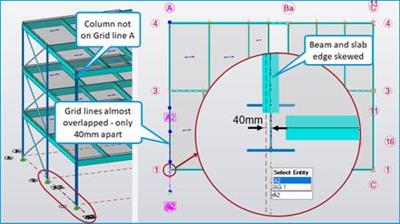
Such poor geometry can result in beams and edges of slabs attached to the off-plane column being slightly skewed on plan, or poor analytical connectivity of these if they are modeled to the adjacent grid line A used by other beams and columns. The new "Planarize" command introduced in this release can help correct such issues.
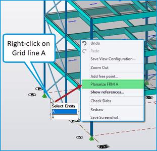
To start the Planarize operation, right-click on the target grid line (the one on which entities are correctly modeled) in any view and select "Planarize FRM..." from the context menu - e.g. on grid line "A" on which the majority of objects in this end frame are placed for the example model, as shown below.
Note that you can also run the Planarize command for a Frame by 1) expanding the Frames branch In the Project Workspace Structure tree then 2) right clicking on the required frame and selecting "Planarize FRM" from the context menu.
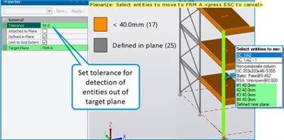
- When the Planarize command is active, the Properties Window will display the settings for it and the scene view will change to highlight only entities that are in the plane and entities that are detected as being close to it, as shown in the picture below. Different colors are used to identify entities defined in, attached to, and near to the target plane, while other entities are not visible.
More information for each highlighted entity, including the specific distance of its nodes from the target plane, can be seen in the tooltip for a selected entity (only highlighted entities out of plane within the tolerance can be selected).
- In the operation properties you set the Tolerance distance (default 25mm/ 1 in) for the detection of entities that are very close to the target plane. We can set for example 50mm in the example case in which the off-plane column and attached entities are 40mm from the plane. The legend gives the description and number of entities for each color category as shown in the picture above.
.Entities in the plane are colored grey and displayed by default - their display being controlled by the "Defined in Plane" check box which is enabled by default.
. Other colors identify objects very close to the plane. There can be a number of colors and associated legend boxes where there are entities with different distances from the target plane within the set tolerance. The colors then range from light orange to red as the distance from the target plane increases.
. You can also enable the option "Attached to Plane" (default Off) to also display entities attached to the target plane.
- To correct the issue, simply select objects to be moved to the target plane. Any of the usual graphical selection methods can be used to select single or multiple entities - for example in this case we can simply window around all the highlighted objects and they are all automatically moved to the target plane.
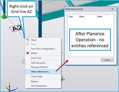
After the operation we can see for the example model that all the entities have been adjusted to reference the target plane grid line (A) and grid line A2 is no longer referenced by any entities.
-[TSD-10505] - Duplication of Base Plate Connections corrected.
In some circumstances, when the base level of a column with an existing base plate connection was adjusted to another level via the Properties Window, the base plate connection could be duplicated. The duplicate was not apparent - as it overlapped the original (at the new base level) - and could cause program errors during subsequent model edits. This is corrected in this release - duplicate base plate connections are no longer created following such edits.
-[TSD-9591] - Update Service Improvement
The Update service is now more resilient if there is a problem with the FlexNet Connect agent installation which previously could cause program crashes.
Note that this fix also requires the 'Tekla Structural Update Service Update November 2021 (1.4.1)' which was released on Friday 26 Nov and can be obtained from Tekla Downloads.
-[TSD-9272] - Support Tool Sign In Update
The Support Tool, which opens when you select "Contact Support" from the file menu, is updated in this release to use the Windows default browser for sign in, rather than the embedded Chrome browser. This can result in slightly changed behavior when opening the Support Tool for the first time during a session, potentially requiring you to sign in again in a default browser window even when already signed in to the program.
Highlights
- Automatic minimum wind loads - USA head code
Other Loading Enhancements and Fixes
- [TSD-10564] - User-defined Wind Load Cases can now be copied
Previously in the Loading dialog the "Copy" option was disabled for all load cases of the Type "Wind" regardless of whether they were user-defined or generated by the Wind Wizard. In this release the Copy option is now enabled for use-defined Wind load cases, making it easier for example to apply simple wind load cases in all directions.
- [TSD-10451] - Seismic Loading - Minimum Lateral Loads no longer listed for Seismic Weight Combination
When Minimum Lateral Loads were activated (Home > Model Settings > Minimum Lateral Loads), they were incorrectly listed for inclusion in the Effective Seismic Weight/ Seismic Inertia page of the Seismic Wizard. This is corrected in this release and they are no longer listed on this page. This issue related only to release 2021 SP3 in which Minimum Lateral Loads were introduced.
In the unlikely event a user included one or more minimum lateral load cases in the Effective Seismic Weight combination it would be invalid with no Class set. This could easily be corrected in the Loading dialog by selecting the Effective Seismic Weight combination and removing the offending Minimum Lateral Load case(s).
-[TSD-10398] - RSA Seismic Analysis Results View - Core Reactions for Envelopes corrected
An incorrect process was previously used to determine the Results View Core Reactions for RSA Seismic Analysis for envelopes, generally resulting in values that were clearly too small. Correct reaction values were reported for combinations in the Results view and in the "Foundation Reactions + Coincident'' report item for envelopes. This issue is corrected in this release.
Note that this issue had no effect on design results - it relates specifically to analysis result reporting for cores only.
-[TSD-9960] - Model & Results - Improved Reporting for Envelope Results
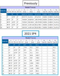
The output of result tables for envelopes in the Tabular Data Model & Results view (and their associated report items) has been improved for situations where previously the max/ min envelope results were reported in a single cell separated by a "/" character. The tables now appear as follows as illustrated in the picture below:
For envelopes, instead of reporting the max/ min results for each node/ entity etc on a single row with the two values in each cell, there are now separate rows for the max and min values with a single value in each cell. The 1st row gives the maximum positive value and the 2nd row the maximum negative value for the action under consideration - e.g. in the Nodal Forces Table, the force at each support node as shown below. This makes the result tables more readily usable in further processes, such as when exported to Excel for further processing.
If positive / negative values for all actions are not present, only a single row is presented for the node / entity etc. under consideration.
This change applies to the following Tabular Data tables and their associated report items; Nodal forces, Nodal deflections, Element end forces, Wall lines, 2D Result lines, Core lines.
-[TSD-10473] - Analysis Speed and RAM Usage improvements
Adjustments to memory allocation procedures during analysis have slightly reduced peak RAM demands for larger models and have also resulted in analysis phase speed improvements typically in the range 20 to 40%
General
-[TSD-9766] - Design Using Tekla Tedds - Preview Results automatically enabled for Timber member design
To enhance the workflow when using Tekla Tedds for timber/ wood members, the Preview results checkbox is now automatically enabled so that the check results are immediately displayed when the Tedds Timber/ Wood member design calculation dialog is displayed.
-[TSD-10379] - Clarification of Design Status Beyond Scope and Other
In previous releases there was an inconsistency in the use of the "Beyond Scope" and "Other" Review View design status categories. This is addressed in this release for all Head Codes - now all columns, beams, braces, truss members, purlins, rails, eaves beams, parapet posts, gable posts etc that cannot be designed in Tekla Structural Designer or using Tekla Tedds are set to status "Beyond Scope" consistently following a design. Hence it is much clearer to the user which entities can currently be designed in Tekla Structural Designer or using Tekla Tedds.
Head Code Australia
-[TSD-10378] - Westok Plated sections no longer designed
Since the specialist Westok Plated section design checks are not available for the Australian Steel design code, beams with Westok Plated sections are no longer designed for the Australian Head Code.
-[TSD-10429] - Concrete Wall Design - Thickness Limit for Out of Plane Shear corrected
For the 2018 year of Concrete Design Resistance Code AS:3600 and walls with no out of plane shear reinforcement specified, the wall thickness limits for the adequacy of unreinforced shear resistance for out of plane shear are corrected to:
Wall thickness tw < 750 mm - unreinforced section sufficient (previously ≤ 750 mm)
Wall thickness tw ≥ 750 mm - unreinforced section inadequate (previously > 750 mm)
Head Code British Standards
-[TSD-6009] - Concrete Beam Design - corrected minimum allowed link diameter check
The minimum allowed link diameter check, which forms part of the link limit checks for reinforced concrete beam design to BS8110-1:1997, has been enhanced in order to improve the accuracy of selection of the longitudinal compression reinforcement bar size to be used in the check. Previously, due to overlapping of the different longitudinal top and bottom reinforcement design regions, the obtained compression bar size in a given shear design region could derive from bars outside that region, which could result in an overestimate of the minimum shear reinforcement bar size. In this release it is now ensured that the longitudinal compression bar size used in the check only considers bars that actually cross the relevant shear design region.
Head Code Eurocode
Highlights
Steel column base plate design - enhanced design for minor axis shear - Eurocode
Other Eurocode Design Enhancements and Fixes
-[TSD-10671] - Steel Column design - buckling combined check - enhanced check positions for multiple restraints within a stack
For the more rare situation of multiple LTB segments within a column stack length - which for beams connecting to the column minor axis only requires the user to manually override the default strut restraint settings to specify restraint to the major axis - the detection of design forces for the buckling combined check is improved to consider only forces at the ends of individual segments, rather than the full stack.
-[TSD-10593] - Punching Shear Design - Update to latest version of Irish NA
I.S. EN 1992-1-1 NATIONAL ANNEX:2004/NA:2010/AC2:2020 is the latest consolidated version of the Irish National Annex to I.S. EN 1992-1-1. In this latest update the National Determined Parameter (N.D.P.) for the maximum allowed punching shear strength calculations has been updated from the previous value of 0.5*v*fcd to 0.4*v*fcd (bringing it into line with EN 1992-1-1 where this value was changed by AC2 in 2010) . The punching shear checks performed by the program - in all areas for both slabs and foundations as appropriate - have been updated accordingly in this release to comply with this.
Head Code USA
-[TSD-10104] - Concrete Seismic Design for UBC Seismic Loading
The seismic design checks made for concrete members have been updated for when the Seismic Loading Code is set to UBC. Previously, specific seismic checks were essentially the same as those made for the ASCE7 Seismic Loading Code, with the principle difference being that the Seismic Design Category (SDC) was set to Unknown (since the UBC loading code uses "Seismic Zones" rather than SDC's), meaning some checks related to SDC's were not performed.
. For this release reference was made to Table R1.1.9.1 originally published in ACI-318-08 table which correlated UBC Seismic Zones (UBC) to SDC's. Now an SDC appropriate to the UBC Seismic Zone is set and ACI-318 seismic checks are performed appropriate to this.
. This change principally affects design for UBC seismic regions 3 and 4 which correspond with SDC D - F, resulting in the following changes for these zones:
Warnings are now also displayed for members not assigned to any SFRS.
Column-beam joint region link spacing checks are now performed accordingly.
The minimum concrete compressive strength check for members that cannot be assigned to an SFRS - such as pad bases, pile caps and foundation mats - is now performed appropriate to the SDC. The design details give the respective seismic zone together with an explanatory note for the Warning status when the minimum is not met.
Reports Highlights
Embodied carbon - New and enhanced review & reporting options
Other Reports Enhancements and Fixes
-[TSD-10397] - Foundation Reactions Report - RSA Seismic Analysis for Envelopes corrected
For the "Foundation Reactions" report item, an incorrect process was previously used to determine the Max/ Min results for RSA Seismic Analysis for envelopes. The issue affected reactions for all entities and reported values could potentially be greater or smaller than the correct values. Where the issue occurred it would generally be evident from clear differences in some Max/ Min values in the report when compared to those given in the Results View and the "Foundation Reactions + Coincident" report item for the same envelope and constituent combinations, both of which give the correct results. This issue is corrected in this release.
Note that this issue had no effect on design results - it relates specifically to analysis result reporting only.
-[TSD-8584] - Improved default Report Page Settings
To improve the appearance of reports and reduce wastage for 'out of the box' settings, the default values for report margins (accessed via Report > Page Setup > Margins) have been reduced. The Table width (Report > Settings > Table Options > Table width) has also been correspondingly slightly increased to 95%. As a result reports should generally be more legible and compact by default.
Drawings
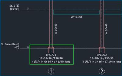
-[TSD-10310] - Drawings - General Arrangement for Frames now includes Base Plate Connections
Base Plates Connections are now included in General Arrangement drawings for Frames (i.e. elevations) as well as planes as previously. The drawing information includes the connection reference and key data such as base plate size and grade and bolt/ rod number, size and grade, as shown in the picture below.
To include base plates in drawings, ensure the "Base Plates" Layers option is enabled in Draw > Settings > Layer Configuration > Planar Drawings for the Drawing Variant(s) - e.g. General Arrangement - should you wish to include them.
Tekla Structural Designerdelivers powerful features for optimizing concrete and steel design, including the ability to quickly compare alternative design schemes, efficiently manage changes and collaborate seamlessly. Regardless of project size or complexity, Tekla Structural Designer's fully automated, productivity-enhancing capabilities enable engineering firms to improve operations, successfully bid more projects and enhance client service.
Tekla Structural Designer 2021 structural analysis and design software introduces the 'design-to-detail workflow' for more efficient modeling of reinforced cast-in-place concrete and transferring reinforcing bars, including slabs, foundations, beams, columns and walls, to Tekla Structures. A new carbon calculator provides the ability to understand a structure's embodied carbon impact during design and compare alternative schemes to identify the most effective, sustainable and affordable option.
Tekla Structural Designer in 5 Minutes
Tekla software solutionsfor advanced BIM and structural engineering are produced by Trimble. Trimble's construction offering ranges from total stations to advanced software, giving the industry tools to transform planning, design, construction and operation of buildings. Tekla software is at the heart of the design and construction workflow, building on the free flow of information, constructible models and collaboration.
Product:Tekla Structural Designer
Version:2021 SP4 (21.4.0.72) Update Only *
Supported Architectures:x64
Website Home Page :
www.tekla.comLanguages Supported:english
System Requirements:PC **
Software Prerequisites:Tekla Structural Designer 2021 and above
Size:107.4 mb
* This service pack requires Tekla Structural Designer 2021 first release (version 21.0.0.116) to be installed and will update your current version.
Buy Premium From My Links To Get Resumable Support,Max Speed & Support Me
https://hot4share.com/0hwwtondn4au/0e5vf.Tekla.Structural.Designer.2021.SP4.Update.rar.html

https://rapidgator.net/file/9d0ca17454482d0a3e26320dd3019223/0e5vf.Tekla.Structural.Designer.2021.SP4.Update.rar.html

https://uploadgig.com/file/download/2cd0A71b925666e7/0e5vf.Tekla.Structural.Designer.2021.SP4.Update.rar

https://nitro.download/view/2D31779259E8158/0e5vf.Tekla.Structural.Designer.2021.SP4.Update.rar
 Views: 23
  Comments (0)
free Tekla Structural Designer 2021 SP4 Update, Downloads Tekla Structural Designer 2021 SP4 Update, RapidShare Tekla Structural Designer 2021 SP4 Update, Megaupload Tekla Structural Designer 2021 SP4 Update, Mediafire Tekla Structural Designer 2021 SP4 Update, DepositFiles Tekla Structural Designer 2021 SP4 Update, HotFile Tekla Structural Designer 2021 SP4 Update, Uploading Tekla Structural Designer 2021 SP4 Update, Easy-Share Tekla Structural Designer 2021 SP4 Update, FileFactory Tekla Structural Designer 2021 SP4 Update, Vip-File Tekla Structural Designer 2021 SP4 Update, Shared Tekla Structural Designer 2021 SP4 Update, Please feel free to post your Tekla Structural Designer 2021 SP4 Update Download, Movie, Game, Software, Mp3, video, subtitle, sample, torrent, NFO, Crack, uploaded, putlocker, Rapidgator, mediafire, Netload, Zippyshare, Extabit, 4shared, Serial, keygen, Watch online, requirements or whatever-related comments here.
Related Downloads :
{related-news}

